How does EVSE work? What are control pilot and proximity contact signals?
The function of control pilot (CP) is explained in Annex A of the IEC standard 61851-1:2017.
The control pilot signal enables basic communication between the EVSE (charger) and EV (electrical vehicle):
The charger sends the information about its maximum charging current in the form of a 1 kHz ±12 V pulse-width modulated (PWM) signal to the electric vehicle. The electric vehicle then reads this signal and determines the maximum charging current it is permitted to draw.
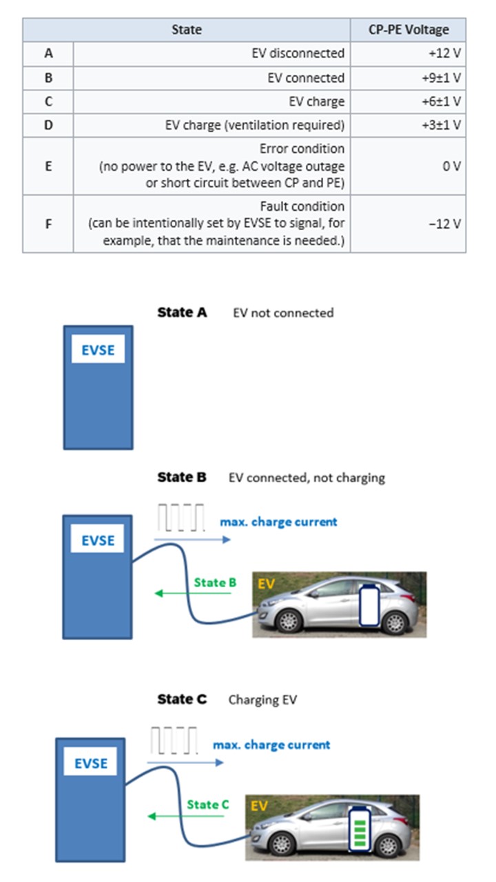
In order to ensure that the charging is done in a safe and controlled manner signalling in the opposite direction is required as well. The standard IEC 61851-1 defines a set of EVSE states shown in the table below. The electric vehicle signals its presents (state B), the request for charging (state C) or request for ventilated charging (state D) by applying a relevant resistor between the control pilot (CP) and protective earth (PE). The charger will enter state B, C or D upon detecting the required voltage across CP-PE (see the table below):
+9V means that an electric vehicle is connected.
when charger detects +6V it enters into charging mode.
when the charger detects +3V it enters into charging mode if it can provide ventilation in the charging area. Not all chargers have this feature.
Besides states B, C and D, several other states are defined:
A – electric vehicle not connected to charger
E – error condition
F – fault condition
The proximity function (PP) is explained in Annex B of standard IEC 61851-1:2017.
Depending on the type of connector, there are two different functions of the proximity contact:
Type 1 connectors have an auxiliary switch (the top part of the connector in Figure 1). The charger detects when the electric vehicle is connected and additionally, whether the switch has been latched or not. The EVSE connector is safely attached to EV only if the auxiliary switch is in latched position.
In case of Type 2 connectors there is no auxiliary switch. The proximity signal is used for simultaneous proximity detection and current capability coding of the cable assembly. The value of the resistor connected between the proximity contact (PP) and the earthing contact (PE) determines the maximum current capability of the cable assembly (e.g. 13A, 20A, 32A, 63A or 70A). When the charger detects a certain value of the resistance it should adjust its maximum current according to the maximum current signalled by the cable resistor. This maximum current value will be then communicated to electric vehicle via the control pilot (CP) communication protocol described above.
This website is using cookies to provide a good browsing experience
These include essential cookies that are necessary for the operation of the site, as well as others that are used only for anonymous statistical purposes, for comfort settings or to display personalized content. You can decide for yourself which categories you want to allow. Please note that based on your settings, not all functions of the website may be available.
Privacy Policy
1. An overview of data protection
General
The following gives a simple overview of what happens to your personal information when you visit our website. Personal information is any data with which you could be personally identified. Detailed information on the subject of data protection can be found in our privacy policy found below.
Data collection on our website
Who is responsible for the data collection on this website?
The data collected on this website are processed by the website operator. The operator's contact details can be found in the website's required legal notice.
How do we collect your data?
Some data are collected when you provide it to us. This could, for example, be data you enter on a contact form.
Other data are collected automatically by our IT systems when you visit the website. These data are primarily technical data such as the browser and operating system you are using or when you accessed the page. These data are collected automatically as soon as you enter our website.
What do we use your data for?
Part of the data is collected to ensure the proper functioning of the website. Other data can be used to analyze how visitors use the site.
What rights do you have regarding your data?
You always have the right to request information about your stored data, its origin, its recipients, and the purpose of its collection at no charge. You also have the right to request that it be corrected, blocked, or deleted. You can contact us at any time using the address given in the legal notice if you have further questions about the issue of privacy and data protection. You may also, of course, file a complaint with the competent regulatory authorities.
Analytics and third-party tools
When visiting our website, statistical analyses may be made of your surfing behavior. This happens primarily using cookies and analytics. The analysis of your surfing behavior is usually anonymous, i.e. we will not be able to identify you from this data. You can object to this analysis or prevent it by not using certain tools. Detailed information can be found in the following privacy policy.
You can object to this analysis. We will inform you below about how to exercise your options in this regard.
2. General information and mandatory information
Data protection
The operators of this website take the protection of your personal data very seriously. We treat your personal data as confidential and in accordance with the statutory data protection regulations and this privacy policy.
If you use this website, various pieces of personal data will be collected. Personal information is any data with which you could be personally identified. This privacy policy explains what information we collect and what we use it for. It also explains how and for what purpose this happens.
Please note that data transmitted via the internet (e.g. via email communication) may be subject to security breaches. Complete protection of your data from third-party access is not possible.
Notice concerning the party responsible for this website
The party responsible for processing data on this website is:
The responsible party is the natural or legal person who alone or jointly with others decides on the purposes and means of processing personal data (names, email addresses, etc.).
Revocation of your consent to the processing of your data
Many data processing operations are only possible with your express consent. You may revoke your consent at any time with future effect. An informal email making this request is sufficient. The data processed before we receive your request may still be legally processed.
Right to file complaints with regulatory authorities
If there has been a breach of data protection legislation, the person affected may file a complaint with the competent regulatory authorities. The competent regulatory authority for matters related to data protection legislation is the data protection officer of the German state in which our company is headquartered. A list of data protection officers and their contact details can be found at the following link: https://www.bfdi.bund.de/DE/Infothek/Anschriften_Links/anschriften_links-node.html.
Right to data portability
You have the right to have data which we process based on your consent or in fulfillment of a contract automatically delivered to yourself or to a third party in a standard, machine-readable format. If you require the direct transfer of data to another responsible party, this will only be done to the extent technically feasible.
SSL or TLS encryption
This site uses SSL or TLS encryption for security reasons and for the protection of the transmission of confidential content, such as the inquiries you send to us as the site operator. You can recognize an encrypted connection in your browser's address line when it changes from "http://" to "https://" and the lock icon is displayed in your browser's address bar.
If SSL or TLS encryption is activated, the data you transfer to us cannot be read by third parties.
Information, blocking, deletion
As permitted by law, you have the right to be provided at any time with information free of charge about any of your personal data that is stored as well as its origin, the recipient and the purpose for which it has been processed. You also have the right to have this data corrected, blocked or deleted. You can contact us at any time using the address given in our legal notice if you have further questions on the topic of personal data.
Opposition to promotional emails
We hereby expressly prohibit the use of contact data published in the context of website legal notice requirements with regard to sending promotional and informational materials not expressly requested. The website operator reserves the right to take specific legal action if unsolicited advertising material, such as email spam, is received.
3. Data collection on our website
Cookies
Some of our web pages use cookies. Cookies do not harm your computer and do not contain any viruses. Cookies help make our website more user-friendly, efficient, and secure. Cookies are small text files that are stored on your computer and saved by your browser.
Most of the cookies we use are so-called "session cookies." They are automatically deleted after your visit. Other cookies remain in your device's memory until you delete them. These cookies make it possible to recognize your browser when you next visit the site.
You can configure your browser to inform you about the use of cookies so that you can decide on a case-by-case basis whether to accept or reject a cookie. Alternatively, your browser can be configured to automatically accept cookies under certain conditions or to always reject them, or to automatically delete cookies when closing your browser. Disabling cookies may limit the functionality of this website.
Cookies which are necessary to allow electronic communications or to provide certain functions you wish to use (such as the shopping cart) are stored pursuant to Art. 6 paragraph 1, letter f of DSGVO. The website operator has a legitimate interest in the storage of cookies to ensure an optimized service provided free of technical errors. If other cookies (such as those used to analyze your surfing behavior) are also stored, they will be treated separately in this privacy policy.
Server log files
The website provider automatically collects and stores information that your browser automatically transmits to us in "server log files". These are:
Browser type and browser version
Operating system used
Referrer URL
Host name of the accessing computer
Time of the server request
IP address
These data will not be combined with data from other sources.
The basis for data processing is Art. 6 (1) (f) DSGVO, which allows the processing of data to fulfill a contract or for measures preliminary to a contract.
Contact form
Should you send us questions via the contact form, we will collect the data entered on the form, including the contact details you provide, to answer your question and any follow-up questions. We do not share this information without your permission.
We will, therefore, process any data you enter onto the contact form only with your consent per Art. 6 (1)(a) DSGVO. You may revoke your consent at any time. An informal email making this request is sufficient. The data processed before we receive your request may still be legally processed.
We will retain the data you provide on the contact form until you request its deletion, revoke your consent for its storage, or the purpose for its storage no longer pertains (e.g. after fulfilling your request). Any mandatory statutory provisions, especially those regarding mandatory data retention periods, remain unaffected by this provision.
4. Analytics and advertising
Google Analytics
This website uses Google Analytics, a web analytics service. It is operated by Google Inc., 1600 Amphitheatre Parkway, Mountain View, CA 94043, USA.
Google Analytics uses so-called "cookies". These are text files that are stored on your computer and that allow an analysis of the use of the website by you. The information generated by the cookie about your use of this website is usually transmitted to a Google server in the USA and stored there.
Google Analytics cookies are stored based on Art. 6 (1) (f) DSGVO. The website operator has a legitimate interest in analyzing user behavior to optimize both its website and its advertising.
Browser plugin
You can prevent these cookies being stored by selecting the appropriate settings in your browser. However, we wish to point out that doing so may mean you will not be able to enjoy the full functionality of this website. You can also prevent the data generated by cookies about your use of the website (incl. your IP address) from being passed to Google, and the processing of these data by Google, by downloading and installing the browser plugin available at the following link: https://tools.google.com/dlpage/gaoptout?hl=en.
Objecting to the collection of data
You can prevent the collection of your data by Google Analytics by clicking on the following link. An opt-out cookie will be set to prevent your data from being collected on future visits to this site: Disable Google Analytics.
We use "Google reCAPTCHA" (hereinafter "reCAPTCHA") on our websites. This service is provided by Google Inc., 1600 Amphitheater Parkway, Mountain View, CA 94043, USA ("Google").
reCAPTCHA is used to check whether the data entered on our website (such as on a contact form) has been entered by a human or by an automated program. To do this, reCAPTCHA analyzes the behavior of the website visitor based on various characteristics. This analysis starts automatically as soon as the website visitor enters the website. For the analysis, reCAPTCHA evaluates various information (e.g. IP address, how long the visitor has been on the website, or mouse movements made by the user). The data collected during the analysis will be forwarded to Google.
The reCAPTCHA analyses take place completely in the background. Website visitors are not advised that such an analysis is taking place.
Data processing is based on Art. 6 (1) (f) DSGVO. The website operator has a legitimate interest in protecting its site from abusive automated crawling and spam.
If you would like to receive our newsletter, we require a valid email address as well as information that allows us to verify that you are the owner of the specified email address and that you agree to receive this newsletter. No additional data is collected or is only collected on a voluntary basis. We only use this data to send the requested information and do not pass it on to third parties.
We will, therefore, process any data you enter onto the contact form only with your consent per Art. 6 (1) (a) DSGVO. You can revoke consent to the storage of your data and email address as well as their use for sending the newsletter at any time, e.g. through the "unsubscribe" link in the newsletter. The data processed before we receive your request may still be legally processed.
The data provided when registering for the newsletter will be used to distribute the newsletter until you cancel your subscription when said data will be deleted. Data we have stored for other purposes (e.g. email addresses for the members area) remain unaffected.
CleverReach
This website uses CleverReach to send newsletters. The supplier is CleverReach GmbH & Co. KG, Mühlenstr. 43, 26180 Rastede. CleverReach is a service which organizes and analyzes the distribution of newsletters. The data you provide (e.g. your email address) to subscribe to our newsletter will be stored on CleverReach servers in Germany.
Sending our newsletters with CleverReach enables us to analyze the behavior of newsletter recipients. Among other things, we can find out how many recipients have opened the email containing the newsletter and how often various links contained therein are clicked. With the help of conversion tracking, we can also analyze whether a predefined action (such as the purchase of a product on our website) takes place after clicking on the link in the newsletter. For more information on how data is analyzed by CleverReach, please visit https://www.cleverreach.com/de/funktionen/reporting-und-tracking/.
Data processing is based on Art. 6 (1) (a) DSGVO. You may revoke your consent at any time by unsubscribing to the newsletter. The data processed before we receive your request may still be legally processed.
If you do not want your usage of the newsletter to be analyzed by CleverReach, you will have to unsubscribe from the newsletter. For this purpose, we provide a link in every newsletter we send. You can also unsubscribe from the newsletter directly on the website.
The data provided when registering for the newsletter will be used to distribute the newsletter until you cancel your subscription when said data will be deleted from our servers and those of CleverReach. Data we have stored for other purposes (e.g. email addresses for the members area) remains unaffected.
Our website uses plugins from YouTube, which is operated by Google. The operator of the pages is YouTube LLC, 901 Cherry Ave., San Bruno, CA 94066, USA.
If you visit one of our pages featuring a YouTube plugin, a connection to the YouTube servers is established. Here the YouTube server is informed about which of our pages you have visited.
If you're logged in to your YouTube account, YouTube allows you to associate your browsing behavior directly with your personal profile. You can prevent this by logging out of your YouTube account.
YouTube is used to help make our website appealing. This constitutes a justified interest pursuant to Art. 6 (1) (f) DSGVO.
For uniform representation of fonts, this page uses web fonts provided by Google. When you open a page, your browser loads the required web fonts into your browser cache to display texts and fonts correctly.
For this purpose your browser has to establish a direct connection to Google servers. Google thus becomes aware that our web page was accessed via your IP address. The use of Google Web fonts is done in the interest of a uniform and attractive presentation of our website. This constitutes a justified interest pursuant to Art. 6 (1) (f) DSGVO.
If your browser does not support web fonts, a standard font is used by your computer.
This site uses the Google Maps map service via an API. It is operated by Google Inc., 1600 Amphitheatre Parkway, Mountain View, CA 94043, USA.
To use Google Maps, it is necessary to save your IP address. This information is generally transmitted to a Google server in the USA and stored there. The provider of this site has no influence on this data transfer.
The use of Google Maps is in the interest of making our website appealing and to facilitate the location of places specified by us on the website. This constitutes a justified interest pursuant to Art. 6 (1) (f) DSGVO.
1. Content
The author reserves the right not to be responsible for the topicality, correctness, completeness or quality of the information provided. Liability claims regarding damage caused by the use of any information provided, including any kind of information which is incomplete or incorrect, will therefore be rejected.
All offers are not-binding and without obligation. Parts of the pages or the complete publication including all offers and information might be extended, changed or partly or completely deleted by the author without separate announcement.
2. Referrals and links
The author is not responsible for any contents linked or referred to from his pages - unless he has full knowledge of illegal contents and would be able to prevent the visitors of his site from viewing those pages.
If any damage occurs by the use of information presented there, only the author of the respective pages might be liable, not the one who has linked to these pages. Furthermore the author is not liable for any postings or messages published by users of discussion boards, guest books or mailing lists provided on his page.
3. Copyright
The author intended not to use any copyrighted material for the publication or, if not possible, to indicate the copyright of the respective object.
The copyright for any material created by the author is reserved. Any duplication or use of objects such as diagrams, sounds or texts in other electronic or printed publications is not permitted without the author's agreement.
4. Privacy policy
If the opportunity for the input of personal or business data (email addresses, name, addresses) is given, the input of these data takes place voluntarily. The use and payment of all offered services are permitted - if and so far technically possible and reasonable - without specification of any personal data or under specification of anonym zed data or an alias. The use of published postal addresses, telephone or fax numbers and email addresses for marketing purposes is prohibited, offenders sending unwanted Spam messages will be punished.
5. Legal validity of this disclaimer
This disclaimer is to be regarded as part of the internet publication which you were referred from. If sections or individual terms of this statement are not legal or correct, the content or validity of the other parts remain uninfluenced by this fact.
Your cookie preferences have been saved.
To load this element, it is required to consent to the following cookie category: {category}.